Dependent value: m
Dependent value: m

| THICKNESS | 0.75 | 1 | 2 | 3 | 4 | 5 | 6 | 8 | 10 | 12 |
| RAGGIO (mm) | 130 | 175 | 300 | 450 | 600 | 750 | 900 | 1200 | 1500 | 1700 |

| Light transmission | |
| Unico impianto con produzione di larghezza fino a 2.500mm | |
| Impact resistance | |
| Reaction to fire Class1 EN 13501-1 [sp. da 8 a 12mm] | |
| Maximum thickness of 20 mm | |
| UV protection on both sides | |
| Reaction to fire EN 13501-1 EuroClass B-s2 d0 [sp. 6mm] | |
| Reaction to fire EN 13501-1 EuroClass B-s1 d0 [sp. da 2 a 5mm] |
Production standard
| THICKNESS | mm | 0.75 | 1 | 2 | 3 | 4 | 5 | 6 | 8 | 10 | 12 | 15 | 20 |
|---|---|---|---|---|---|---|---|---|---|---|---|---|---|
| Width | mm | 1000 | 1000 | 2050-2500 | 2050-2500 | 2050-2500 | 2050-2500 | 2050-2500 | 2050-2500 | 2050-2500 | 2050-2500 | 2050-2500 | - |
| Length | mm | 2050 | 2050 | 6100 | 6100 | 6100 | 6100 | 6100 | 6100 | 6100 | 6100 | 6100 | - |
| Massa areica | Kg/m² | 0,9 | 1,2 | 2,4 | 3,6 | 4,8 | 6 | 7,2 | 9,6 | 12 | 14,4 | 18 | 24 |
| Glass weight | Kg/m² | - | - | 5 | 7,5 | 10 | 12 | 15 | 20 | 25 | 30 | - | 50 |
| Thermal insulation Uhor | W/m² | 5,8 | 5,7 | 6,7 | 6,5 | 6,3 | 6,1 | 5,9 | 5,6 | 5,3 | 5 | 4,7 | - |
| Thermal insulation Uver | W/m² | - | - | 5,6 | 5,4 | 5,3 | 5,1 | 5,0 | 4,8 | 4,5 | 4,3 | 4,1 | - |
| Thermal insulation glass | W/m²K | - | - | 5,87 | 5,82 | 5,8 | 5,77 | 5,71 | - | - | - | - | |
| Acustic insulation | dB | - | - | 25 | 26 | 27 | 28 | 29 | 31 | 33 | 34 | 36 | - |
| Trasmissione luminosa cristallo | τv | 91 | 91 | 90 | 89 | 88 | 87 | 86 | 85 | 83 | 79 | 77 | - |
| Light transmission bronze | τv | - | - | 65 | 61 | 47 | 43 | 34 | 27 | 20 | 15 | - | - |
| Light transmission light blue | τv | - | - | 68 | 62 | 57 | 52 | 47 | 41 | 40 | 39 | - | - |
| Light transmission opal | τv | - | - | 47 | 36 | 34 | 27 | 18 | 15 | 13 | 11 | - | - |
| Light transmission green | τv | - | - | 83 | 79 | 75 | 71 | 67 | 59 | 53 | 48 | - | - |
| Trasmissione luminosa grigia | τv | - | - | 78 | 72 | 64 | 56 | 55 | 45 | 39 | 33 | - | - |
60(daN/m²)
90(daN/m²)
120(daN/m²)
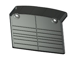
The system's flow rate values differ depending on the type of application. Click on the following icons to see the centre-to-centre distances required based on the permissible load.
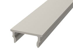
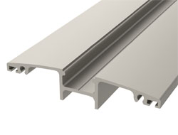
Policomp® and Scudo® sheets can be cold machined by cutting, bending and drilling, using standard high-speed equipment. Notches that negatively affect the mechanical properties of polycarbonate should be avoided.
| CUTTING | Circular saw | Band saw | Milling cutter |
| Relief angle | 20° - 30° | 20° - 30° | 20° - 30° |
| Rake angle | 15° | 0.5° | 0° - 5° |
| Cutting speed (m/min) | 1,800 - 2,400 | 600 - 1,000 | 100 - 500 |
| Feed speed (m/min) | 19 - 25 | 20 - 25 | 0.1 - 0.5 |
| Gear tooth pitch (mm) | 2 - 5 | 1.5 - 2.5 | - |
For bonding solid polycarbonate sheets, only neutral adhesives compatible with polycarbonate must be used.
Policomp® and Scudo® sheets can be drilled with standard drills. To avoid damage to the sheets during processing, the following guidelines are recommended: The hole must be at a minimum distance from the sheet edge equal to 1.5 × the hole diameter; do not use cutting oil; use threaded fasteners when no other alternatives are available; after notching the sheet may break.
| Parameter | Value |
| Relief angle α | 5° - 8° |
| Point angle ψ | 90° - 130° |
| Helix angle β | ~ 30° |
| Rake angle γ | 3° - 5° |
| Cutting speed | 10-60 rpm |
| Feed per revolution | 0.1-0.5 mm/rev |
Before thermoforming, remove the protective films and preheat at 120°C to eliminate absorbed moisture. The use of air-circulation ovens with temperature control is recommended. Air must circulate between the sheets. Storage in a dry place reduces preheating time in an oven by one third. Since moisture reabsorption begins when the temperature of the dry sheet drops below 100°C, thermoforming must take place immediately after drying. For hot bending, a temperature between 155°C and 165°C is recommended.
Solid polycarbonate sheets can be installed in most structures and frames in PVC, wood, steel and aluminum. The frame must hold the sheet in place while allowing it to expand. Sheet thickness is defined based on the required load values. Based on sheet dimensions, from table A the effective area is determined, and thus the thickness. From table B, based on sheet dimensions (AREA) and the required load rating, the sheet thickness to be used is determined. The values shown in table B (in pressure and suction) are defined considering sheets fixed on four sides, with a maximum deflection (rise) of 50 mm.
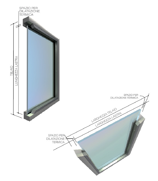
Particular attention must be paid during sheet cutting to ensure sufficient space for thermal expansion, avoiding stresses on the material. Tolerance must be provided both in width and in length. Based on frame dimensions, the adjacent table shows the trimming value of the sheets to allow thermal expansion of the sheets. The edge engagement must have sufficient depth to allow material expansion and prevent the sheet from coming out of the frame.
| FRAME (mm) | Sheet trimming (mm) |
| 300 - 1,000 | 3 |
| 1,000 - 1,300 | 4 |
| 1,300 - 1,700 | 5 |
| 1,700 - 2,000 | 6 |
| 2,000 - 2,300 | 7 |
| 2,300 - 2,700 | 8 |
| 2,700 - 3,000 | 9 |
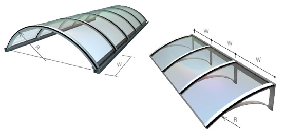
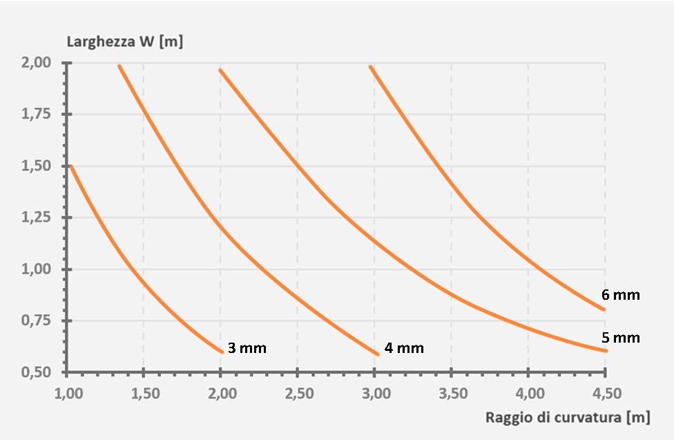
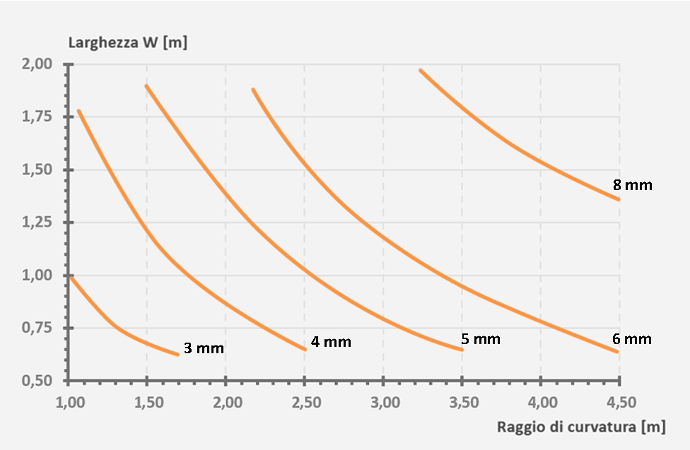
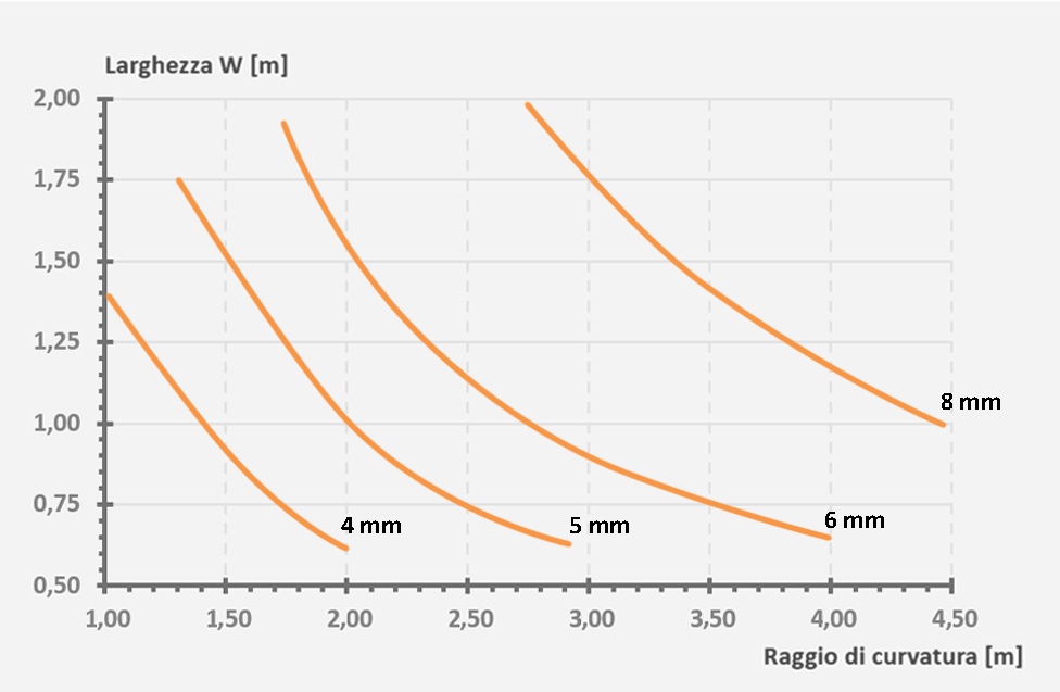
Policomp® is ideally suited for the construction of integral arched structures (tunnel type). The minimum bending radius shall be equal to 150 times the sheet thickness. The choice of sheet thickness depends not only on the bending radius R, but also on the sheet width W. The length L must always be greater than the width W.
Example:
Sheet thickness: 3 mm
Min. radius = 3 × 150 = 450 mm